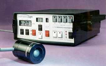
ILT1700 라디오메타 | IL1700 RESEARCH RADIOMETER
페이지 정보
작성자 디티엑스 작성일22-02-11 11:33 조회523회 댓글0건본문
IL1700 RESEARCH RADIOMETER
|
|
|
FRONT PANEL CONTROLS
REAR PANEL
The 'ZERO' button nulls the ambient signal to zero. The 'D.C.' button selects direct measurement mode. The 'INT' button selects light dose integration mode. The 'HOLD' button freezes the display and sends data to the optional printer.
The 'AUTO RANGE' button selects either automatic or fixed range. The 'AUTO 100%' button sets the displayed signal to 100 percent.
The '5 V BIAS' button provides an additional 5 volt reverse bias for flash integrations and for all vacuum photodiode detectors.
The 'DATA/FACTOR DISPLAY' button selects either detector output or sensitivity factor display.
The 'FACTOR SELECT' button increments through the 10 sensitivity factor memory registers.
The 'MSD', 'LSD' and 'EXP' buttons allow the user to adjust the sensitivity factor.
The 'POWER' button turns the power on/off.
An AUTO SHUT-OFF feature automatically turns off the instrument if idle for more than 10 minutes in battery mode.
'BAT' and 'AC' LED's indicate the power source, with low battery warning.
The 'CHG' LED indicates batteries recharging.
The 'OUTPUT RECORDER/TTL' port allows simultaneous autoranging analog recorder output (0-1 volt) and TTL digital data (0-5 volts).
The 'AC VOLTAGE' switch selects 115 or 230 VAC.
The 'COMPUTER/PRINTER' switch configures the standard 'RS232C DIGITAL OUTPUT' connector to match DTE or DCE equipment.
The 'SOURCE AC/BAT' switch selects AC or battery power.
The '90-130/180-240 VAC' power input plug accepts the provided AC power cable.
The detector cable plugs into the 'SENSOR INPUT', which also provides voltages of +15 V, 5 V, and -9 V for various sensor probes.
The 24 line, card edge connector labeled 'ACCESSORY INPUT' allows various input/output functions: auxiliary power input, recorder output, RAM voltage check for constant memory, and remote operation of 'ZERO', 'D.C.', 'INT', and 'HOLD' functions.
ELECTRICAL / MECHANICAL:
Dynamic
Range: 2 x 10-13 to 2 x 10⁻³ A.
Min.
Resolution: 0.01 x 10⁻¹¹ Amperes.
Linearity: ±0.1%, top
8 decades; ±0.2%, ±1 digit, bottom 2 decades.
Display: 3 1/2 digit + 1
1/2 digit exp.
Display Range: 1.000 x 10⁻¹⁹ to 9.99 x
10+19 display units.
Input Impedance: Virtual Ground
(op-amp summing node).
AC Power: 90-130 / 180-240 V, 50-400
Hz.
DC Power: 8-15 V external, or 6 internal 'C' cells.
Max
Power: 11 Watts.
RS232C Output: DTE or DCE, ± 8 V.
TTL
Output: 0 to 5 V.
Recorder Output: 408 Ω impedance, 100 to 1000
mV, ranging every decade, current limited.
Size: 90 mm x 220 mm x 240
mm (3.5" x 8.7" x 9.4").
Weight: 2.3 kg (5.1 lbs.).


